
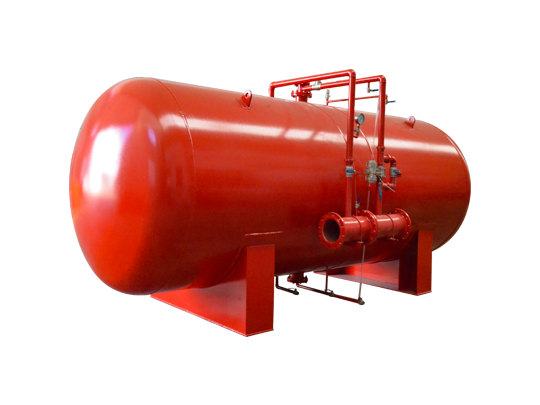

1. Pressure Tank: Assisting in Pipeline Pressure Management
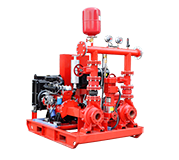
The pressure tank is a key component of this type of fire pump set; with appropriate system design, it buffers minor pressure variations within the pipeline network. When system pressure fluctuates slightly, the tank provides a buffer volume, working alongside the pressure-maintaining pump and control devices to stabilize network pressure. Its volume and rated pressure must be selected based on the system's pressure range, pressure maintenance requirements, and pump set parameters.
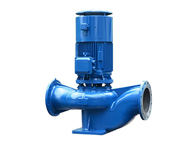
2. Electric Fire Pump: Providing Primary Water Supply Capacity
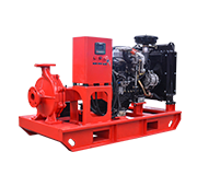
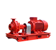
The electric fire pump serves as the system's core water supply unit, responsible for delivering the design-specified water volume during a fire event. Depending on project requirements regarding flow rate, head, and installation conditions, various pump configurations—such as end-suction pumps, horizontal split-case pumps, or multistage pumps—may be selected. Properly matching motor power with pump performance ensures the equipment operates at target conditions while meeting the design specifications of the fire water network.
3. Pressure-Maintaining Pump: Reducing Unnecessary Main Pump Starts
Typically characterized by low flow and high head, the pressure-maintaining pump compensates for minor pressure losses in the pipeline network. Working with the pressure tank and control devices, it handles routine pressure maintenance, preventing the main fire pump from starting frequently due to slight pressure drops. Its flow rate, head, and start/stop pressure settings are determined by the system design and coordinated with the main pump's control logic.
4. Control Cabinet: Supporting Equipment Operation and Management
The control cabinet manages pump set operations according to the design logic and, depending on the configuration, provides functions such as operational status display, pressure signal reception, and fault alarms. Some systems can also be configured with protection functions—such as overload and overcurrent protection—to assist maintenance personnel in identifying anomalies. The specific functions of the control cabinet should align with motor specifications, control methods, and project requirements; installation and commissioning must adhere to the manufacturer's instructions and applicable standards.
5. Auxiliary Monitoring via Pressure Gauges and Sensors
Pressure gauges provide a visual display of pressure readings within the piping network or equipment, while pressure sensors transmit pressure fluctuations to the control system, generating signals for automatic control. Used together, they enable operators to monitor the system's operating status and verify that pressure levels remain within the set range. Appropriate measurement ranges and installation locations should be selected, and the accuracy, wiring, and signal feedback of the instruments should be checked regularly.
6. Piping and Valve Configuration Affects System Performance
Complete fire pump assemblies can be configured with accessories such as suction and discharge piping, check valves, gate valves, flanges, and flexible joints, in accordance with the design. A well-planned piping layout minimizes unnecessary flow resistance and facilitates equipment connection, isolation, and maintenance. Valve specifications, pipe diameters, and connection methods must meet design flow and pressure requirements, while sufficient space must be reserved for equipment inspection, disassembly, and routine maintenance.
7. Common Baseplates Facilitate Integrated Equipment Layout
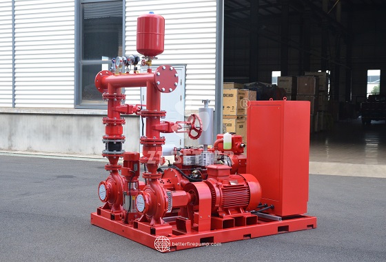
Centralizing the arrangement of the pump, motor, pressure tank, and related components enhances the overall integration of the equipment assembly. A common baseplate simplifies on-site positioning and installation planning, and allows for the factory pre-assembly of certain piping and accessories. During actual installation, factors such as foundation load-bearing capacity, equipment leveling, piping stress, and maintenance access must still be verified to prevent operational issues or future maintenance difficulties caused by improper installation conditions.
8. Material Selection Must Suit the Operating Environment
Materials for the pump body, impeller, shaft, and sealing components of the fire pump assembly must be selected based on water quality, operating pressure, and environmental conditions. Common configurations utilize materials such as cast iron, stainless steel, and bronze, each offering distinct characteristics regarding corrosion resistance, mechanical properties, and cost. For projects involving special water quality or corrosion risks, the suitability of wetted parts and sealing materials requires careful evaluation to ensure the equipment is compatible with actual operating conditions.
9. Rational Equipment Selection Based on Project Parameters
9. Rational Equipment Selection Based on Project Parameters
When selecting an electric fire pump assembly equipped with a pressure tank, comprehensive consideration must be given to design flow rate, total head, pipeline resistance, fire water source conditions, power supply parameters, and installation space. The pressure tank's volume and rated pressure, the operating point of the pressure-stabilizing pump, and the performance curve of the main pump must be mutually compatible. For fire protection systems, applicable fire safety regulations and technical specifications must also be verified; equipment suitability cannot be determined solely based on pressure tank size or motor power.
10. Regular Maintenance to Ensure Long-Term Operation
To maintain the fire pump assembly in optimal condition, a schedule for regular inspections and testing should be established. Maintenance activities may include inspecting the pressure tank and connection points, verifying pipeline network pressure readings, testing control cabinet functions, checking valve status, inspecting pump bodies and piping for leaks, and testing the motor and pump as required. Maintenance personnel should record inspection results and promptly address any anomalies. Specific inspection intervals and testing procedures must adhere to the equipment manual and applicable project fire safety requirements.
Electric fire pump assemblies with pressure tanks provide hydraulic delivery and routine pressure management support for fire water supply systems through the coordinated configuration of main fire pumps, pressure-stabilizing pumps, pressure tanks, control cabinets, and pressure monitoring components. Their advantages lie not only in the equipment combination and installation layout but also in the ability of various components to share water supply, pressure stabilization, and monitoring tasks according to the system design. By rationally matching flow rate, head, pressure tank volume, and control parameters—combined with proper installation and regular maintenance—the alignment between the equipment and project requirements can be enhanced, providing suitable equipment solutions for fire water supply systems in industrial and commercial buildings.
 WhatsApp me