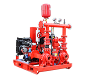
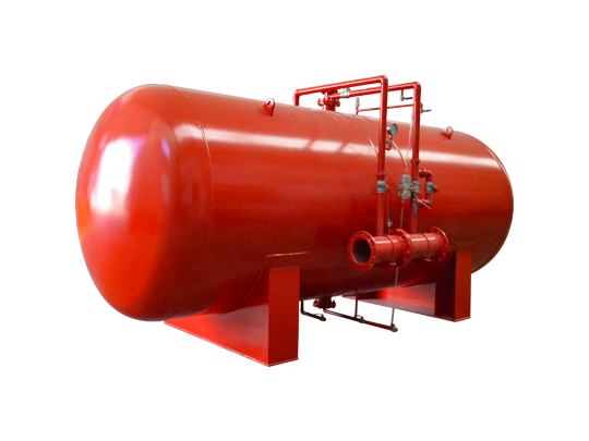

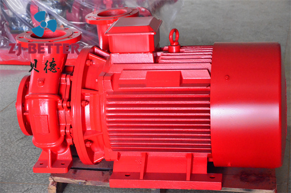
The main components inside the integrated prefabricated pumping station:
1, Requirements for fire pump performance parameters
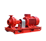
Ordinary fire pump
Working condition 1: When the suction depth is 1m, the requirements of rated flow rate (Qn) and rated pressure (Pn) should be met, and the working pressure should not exceed 1.05 times of the rated pressure.
Working condition 2: When the suction depth is 1m, the flow rate is 1.5 Qn, and the working pressure should not be less than 0.65 Pn.
The maximum working pressure shall not exceed 1.4 Pn.
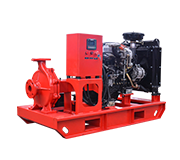
Deep well, submersible fire pump
Working condition 1: When the suction depth is 0m, the requirements of rated flow (Qn) and rated pressure (Pn) should be met, and the working pressure should not exceed 1.05 times of the rated pressure.
Working condition 2: When the suction depth is 0m, the flow rate is 1.5 Qn, and the working pressure should not be less than 0.65 Pn.
The maximum working pressure shall not exceed 1.4 Pn.
2,structural requirements, corrosion resistance performance, mechanical performance, continuous operation and other performance testing should meet the requirements of the GB6245-2006 standard.
3,The pumps used in the pump set shall pass the type identification and type inspection and meet the relevant standards. The selected prime movers should be identified and meet the relevant standards. The engine should have good starting performance at room temperature and should ensure a smooth start within 5s. Within 20s after the water is diverted, the fire pump should be able to reach the rated working condition.
4,The impeller of the water pump rotates flexibly without jamming.
5,Designers should select and determine the type of fire pump according to the location and area of the fire pump room in the project and the specific conditions of the fire water supply system.
6,The flow and pressure of the fire pump should be calculated and determined according to the requirements of the building (or factory area, residential area), storage yard, storage tank, etc. for the fire water volume and pressure. The fire water pump shall meet the water pressure and flow requirements of fire water. The flow rate and head of the water pump shall not be lower than the design requirement value, nor shall it be lower than the given value of the performance curve.
7,The fire water pumps of the temporary high-pressure fire water supply system should be used for one standby and one for use, or for multiple uses and one for standby. The working capacity of the standby fire pump shall not be less than that of the largest one of the fire service pumps. When multiple fire pumps are used as a backup, the impact on system flow and pressure when multiple fire pumps work in parallel should be considered.
8,When choosing a fire pump, its flow-pressure (Q-P) characteristic curve should be flat without humps. When conditions permit, a water pump unit with integrated tangential pump or pump valve (pressure-reducing and stabilizing valve) can be selected.