
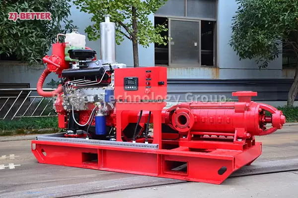
A multistage fire pump is a type of firefighting equipment that uses multiple stages of centrifugal pumps to increase the pressure of the water before it is delivered to the firefighting system. Multistage fire pumps are used in large buildings and commercial properties where the water pressure needs to be increased in order to reach the higher floors of the building or to reach farther distances. Multistage fire pumps are typically powered by diesel or electric motors and can be used with a variety of water sources, including municipal water, rivers, lakes, and wells. They are designed to deliver a constant flow rate and pressure even when there is fluctuating demand from the firefighting system. How to Improve the Working Efficiency of Multistage Fire Pump?
How to Improve the Working Efficiency of Multistage Fire Pump?
2023-05-11
Appropriately reduce the gap of each part or lengthen the sealing gap and adopt labyrinth seal to increase leakage resistance and reduce volume loss. Leakage in the multistage centrifugal pump occurs at the impeller and seal ring, the axial force balance device, etc.
Improve the piping system and reduce resistance. The length of the pipeline should be as short as possible and kept straight, and the flow rate should be reduced to reduce the head loss along the way; the number of gate valves, bottom valves, elbows, orifice plates and other components should be reduced to reduce local head loss.
Reduce the margin of outlet water pressure of the multi-stage centrifugal pump to properly meet the requirements of the pipeline system for outlet water pressure. If the pressure margin of the multistage centrifugal pump is too large, and the outlet pressure of the multistage centrifugal pump is higher than the pressure required by the system, it is necessary to adopt throttling methods such as closing small valves to reduce the pressure, resulting in waste of power. At this time, measures must be taken to transform the multi-stage pump. The first and second-stage impellers can be removed according to the pressure required by the system; Centrifugal pumps try to work at the best efficiency point of the pump, and avoid working at high or low flow rates (lower efficiency points).
①The blade extends and thins toward the suction inlet, so that the liquid is affected by the blade earlier, which can reduce the outer diameter of the impeller and increase the length of the streamline in the blade passage to reduce the relative diffusion; If the Et area is too small, the wall angle between the blade inlet and the blade cover becomes smaller, which increases the hydraulic friction loss and squeezes the inlet flow channel, which is not good for cavitation and efficiency.
②The ratio of the outlet and inlet area of the flow channel between adjacent blades is controlled within the range of 1.0 to 1.3 to reduce the diffusion loss. If the ratio is greater than 1.3, the channel will diffuse seriously and the efficiency will decrease.
③ Increase the width of the impeller outlet and reduce the absolute speed of the impeller outlet, thereby reducing the hydraulic loss in the pressurized water chamber.
④ Obliquely cut the outlet of the impeller, reduce the length difference of the front and rear streamlines or select different blade outlet angles for different streamlines, so as to reduce the pressure difference of the front and rear cover streamlines, thereby reducing the secondary return flow at the outlet.
⑤ Due to the large hydraulic loss of the curved diffuser tube, most of them now use a slightly curved diffuser section that is close to a straight line. For the anti-guide vane, its inlet angle and its position in the circumferential direction should be determined in conjunction with the flow of the liquid flow out of the diffusion section. The principle is to form a continuous flow channel to avoid too narrow the inlet cross-section of the anti-guide vane. Otherwise, vortex and impact losses will be caused at the inlet of the anti guide vane. The larger the hydraulic radius of the flow channel, the better. Make the blade inlet section as close to a square as possible to reduce friction loss. According to hydraulics, the ratio of the cross-sectional area of the water to the wetted area is called the hydraulic radius, that is, the hydraulic radius-the cross-sectional area of the water / Wet week. A large wetted area means that the contact area between the liquid and the wall is large. When the cross-section of the flow channel is changed from an approximate square to a narrow and long rectangle, the liquid is essentially allowed to flow through the gap in the long and narrow cross-section, so the resistance must be large.
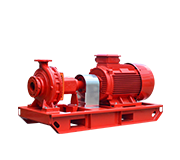
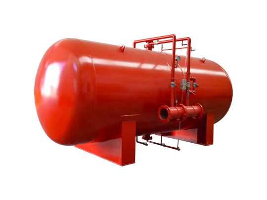
Self-balancing multistage centrifugal pump
⑥ The larger the hydraulic radius of the flow channel, the better. Make the blade inlet cross-section as close to a square as possible to reduce friction loss. According to hydraulics, the ratio of the cross-sectional area to the wetted area is called the hydraulic radius, that is, the hydraulic radius-the cross-section Area/Wet Perimeter. A large wetted area means that the contact area between the liquid and the wall is large. When the cross-section of the flow channel is changed from an approximate square to a narrow and long rectangle, the liquid is essentially allowed to flow through the gap in the long and narrow cross-section, so the resistance must be large.
⑦ Due to the pre-swirl caused by the outlet angle of the anti-guide vane has a great influence on the characteristics of the next-stage impeller, in order to make the "1Vul item in the theoretical lift formula Ht-U2Vu2-"lVul zero, the anti-guide vane It seems that the exit angle of 90 should be selected. , which eliminates the rotational component for the final guide vane. However, experiments have shown that this is not good for efficiency and stable performance curves, especially for some low specific speed pumps, in order to obtain a declining characteristic curve, the outlet angle of the anti-guide vane should be selected to be less than 90°, usually 60°-80° . The ends of the blades are thinner to avoid impact and eddy current losses.
⑧ Increase the throat area of the pressurized water chamber. When the original design area is small, the flow will not be blocked.
①Mechanical friction losses caused by bearings and fillers are generally small and have little effect on efficiency. The mechanical friction loss of the packing seal is larger than that of the mechanical seal.
② Improve the smoothness of the impeller and guide vane runner surface. If possible, it is best to grind the surface of the flow channel with tools such as hand-held grinding wheels, so that the hydraulic friction loss will be significantly reduced.
③ Disc friction loss caused by the surface of the front and rear cover plates of the impeller and the liquid. Choosing a larger blade outlet angle can reduce the outer diameter of the impeller, thereby reducing the disc friction loss. Disc friction loss has a lot to do with surface roughness, so the outer wall of the impeller cover should be as smooth as possible. Appropriately reducing the gap between the impeller cover plate and the guide vane can also reduce the disc friction loss.